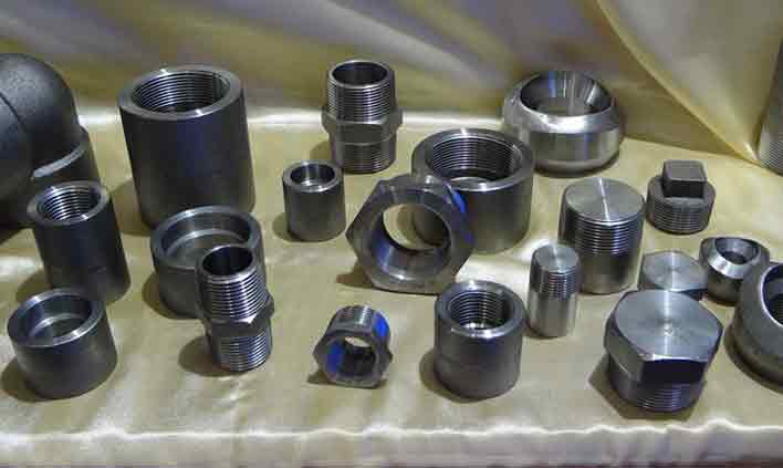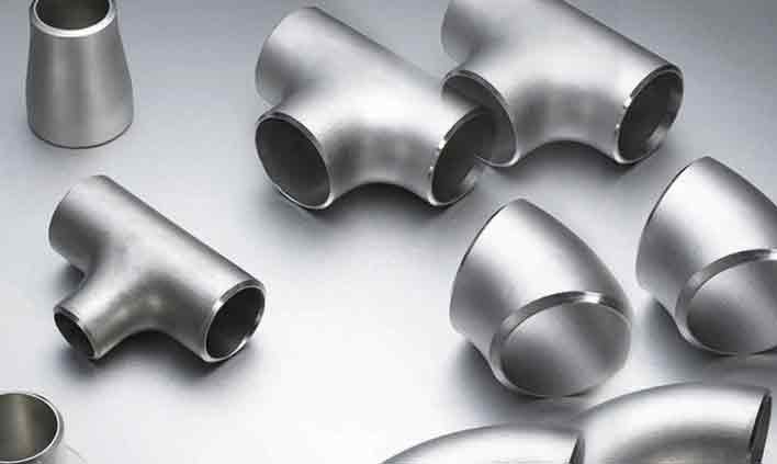
Tubewell Steel & Engg. Co. is a leading manufacturer and stockist specializing in Alloy Steel Pipes, Tubes, Fittings and Flanges for critical industrial applications.
1.25% Chromium – 0.5% Molybdenum forged flanges in Class 1, 2 and 3 for steam, boiler and refinery piping at elevated temperatures.
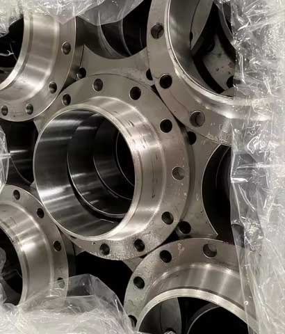
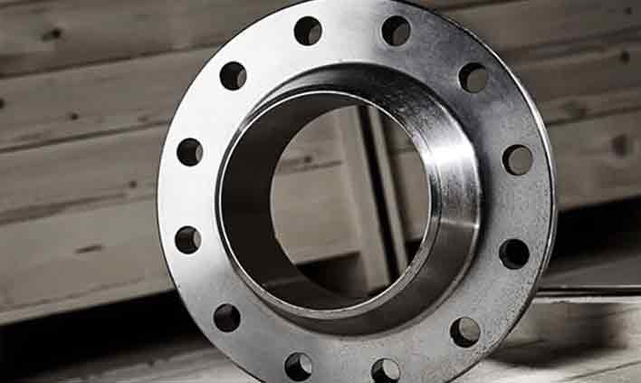
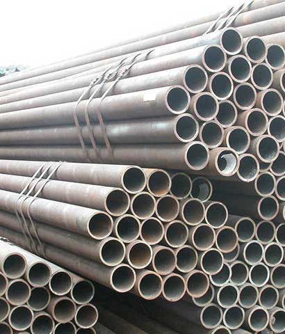
Tubewell Steel & Engg. Co. manufactures, stocks and supplies ASTM A182 F11 flanges in Class 1, 2 and 3 from Mumbai, India. F11 is the most widely used chrome-moly flange grade – it combines good creep strength, oxidation resistance and weldability, and is the standard mating flange for A335 P11 steam and refinery piping.
The workhorse chrome-moly flange for steam and moderate-temperature service
ASTM A182 F11 is a 1.25% chromium – 0.5% molybdenum low-alloy steel produced in three strength classes. Class 1 (415 MPa tensile) has the lowest carbon and best weldability, Class 2 (485 MPa) is the most commonly specified grade for B16.5 flanges, and Class 3 (515 MPa) provides the highest strength. Chromium improves oxidation and sulphidation resistance while molybdenum lifts creep strength for service up to about 595°C.
Our F11 flanges are forged from certified steel, annealed or normalized and tempered at a minimum of 620°C per ASTM A182, then CNC machined to ASME B16.5, B16.47, MSS SP-44 or EN 1092-1. Bores are matched to the connecting A335 P11 pipe, faces are serrated for spiral-wound gaskets, and every piece is marked with grade, class, size and heat number. IBR certification, EN 10204 3.1 / 3.2 documents and TPI are available.
Standard supply range for ASTM A182 F11 flanges
| Parameter | Details |
|---|---|
| Material Standard | ASTM A182, ASME SA182 |
| Grade | F11 Class 1 (UNS K11597), Class 2 & Class 3 (UNS K11572) |
| Dimension Standard | ASME B16.5 (1/2" – 24"), ASME B16.47 Series A & B (26" – 48"), MSS SP-44, EN 1092-1 |
| Size | 1/2" NB to 48" NB (DN 15 – DN 1200) |
| Pressure Class | ASME Class 150, 300, 600, 900, 1500, 2500 |
| PN Rating | PN6, PN10, PN16, PN25, PN40, PN64 |
| Flange Types | Weld Neck, Slip-On, Blind, Socket Weld, Threaded, Lap Joint, RTJ, Long Weld Neck, Reducing, Orifice, Spectacle Blind |
| Facing | Raised Face (RF), Flat Face (FF), Ring Type Joint (RTJ), Tongue & Groove, Male & Female |
| Face Finish | Serrated 125 – 250 µin Ra (3.2 – 6.3 µm), smooth finish on request |
| Bore / Schedule | SCH 10 to SCH XXS, to match A335 P11 pipe |
| Heat Treatment | Annealed or Normalized & Tempered (tempering min. 620°C / 1150°F) |
| B16.5 Material Group | Group 1.9 (F11 Class 2) |
| Testing | PMI, Hardness, Tensile, Impact, UT, MPI / DPT, Visual & Dimensional |
| Certificates | EN 10204 3.1 / 3.2, IBR Certification, NACE MR0175, TPI Reports |
International equivalents of A182 F11
| Grade | ASTM / ASME | UNS | EN 10222-2 | W.Nr. | JIS G3203 | Nominal |
|---|---|---|---|---|---|---|
| F11 Cl.1 | A182 F11 Cl.1 | K11597 | 13CrMo4-5 | 1.7335 | SFVAF11A | 1.25Cr-0.5Mo |
| F11 Cl.2 | A182 F11 Cl.2 | K11572 | 13CrMo4-5 | 1.7335 | SFVAF11A | 1.25Cr-0.5Mo |
| F11 Cl.3 | A182 F11 Cl.3 | K11572 | 13CrMo4-5 | 1.7335 | SFVAF11B | 1.25Cr-0.5Mo |
Equivalents are the nearest comparable grades for reference; confirm suitability against the governing design code before substitution.
Weight %, as per ASTM A182
| Grade | C | Mn | P | S | Si | Cr | Mo |
|---|---|---|---|---|---|---|---|
| F11 Class 1 | 0.05 – 0.15 | 0.30 – 0.60 | 0.030 max | 0.030 max | 0.50 – 1.00 | 1.00 – 1.50 | 0.44 – 0.65 |
| F11 Class 2 | 0.10 – 0.20 | 0.30 – 0.80 | 0.040 max | 0.040 max | 0.50 – 1.00 | 1.00 – 1.50 | 0.44 – 0.65 |
| F11 Class 3 | 0.10 – 0.20 | 0.30 – 0.80 | 0.040 max | 0.040 max | 0.50 – 1.00 | 1.00 – 1.50 | 0.44 – 0.65 |
Minimum values at room temperature
| Grade | Tensile Strength | Yield Strength (0.2%) | Elongation (in 2") | Reduction of Area | Hardness (HBW) |
|---|---|---|---|---|---|
| F11 Class 1 | 415 MPa (60 ksi) min | 205 MPa (30 ksi) min | 20% min | 45% min | 121 – 174 |
| F11 Class 2 | 485 MPa (70 ksi) min | 275 MPa (40 ksi) min | 20% min | 30% min | 143 – 207 |
| F11 Class 3 | 515 MPa (75 ksi) min | 310 MPa (45 ksi) min | 20% min | 30% min | 156 – 207 |
Typical values (for reference)
| Property | Metric | Imperial |
|---|---|---|
| Density | 7.75 g/cm³ | 0.280 lb/in³ |
| Melting Range | 1450 – 1510 °C | 2640 – 2750 °F |
| Modulus of Elasticity | 205 GPa | 29.7 × 10³ ksi |
| Thermal Conductivity (100°C) | 37 W/m·K | 21.4 BTU/h·ft·°F |
| Mean Thermal Expansion (20–300°C) | 12.4 µm/m·°C | 6.9 µin/in·°F |
| Specific Heat | 0.46 J/g·°C | 0.11 BTU/lb·°F |
| Max. Service Temperature | ≈ 595 °C | ≈ 1100 °F |
ASME B16.5 Class 150 & Class 300 flanges – dimensions in mm
| NPS | Cl.150 OD | Cl.150 Thk | Cl.150 BCD | Cl.150 Bolts | Cl.300 OD | Cl.300 Thk | Cl.300 BCD | Cl.300 Bolts | RF Dia |
|---|---|---|---|---|---|---|---|---|---|
| 1/2" | 90 | 9.6 | 60.3 | 4 × 1/2" | 95 | 12.7 | 66.7 | 4 × 1/2" | 34.9 |
| 3/4" | 100 | 11.2 | 69.9 | 4 × 1/2" | 115 | 14.3 | 82.6 | 4 × 5/8" | 42.9 |
| 1" | 110 | 12.7 | 79.4 | 4 × 1/2" | 125 | 15.9 | 88.9 | 4 × 5/8" | 50.8 |
| 1 1/4" | 115 | 14.3 | 88.9 | 4 × 1/2" | 135 | 17.5 | 98.4 | 4 × 5/8" | 63.5 |
| 1 1/2" | 125 | 15.9 | 98.4 | 4 × 1/2" | 155 | 19.1 | 114.3 | 4 × 3/4" | 73.0 |
| 2" | 150 | 17.5 | 120.7 | 4 × 5/8" | 165 | 20.7 | 127.0 | 8 × 5/8" | 92.1 |
| 2 1/2" | 180 | 20.7 | 139.7 | 4 × 5/8" | 190 | 23.9 | 149.2 | 8 × 3/4" | 104.8 |
| 3" | 190 | 22.3 | 152.4 | 4 × 5/8" | 210 | 27.0 | 168.3 | 8 × 3/4" | 127.0 |
| 4" | 230 | 22.3 | 190.5 | 8 × 5/8" | 255 | 30.2 | 200.0 | 8 × 3/4" | 157.2 |
| 5" | 255 | 22.3 | 215.9 | 8 × 3/4" | 280 | 33.4 | 235.0 | 8 × 3/4" | 185.7 |
| 6" | 280 | 23.9 | 241.3 | 8 × 3/4" | 320 | 35.0 | 269.9 | 12 × 3/4" | 215.9 |
| 8" | 345 | 27.0 | 298.5 | 8 × 3/4" | 380 | 39.7 | 330.2 | 12 × 7/8" | 269.9 |
| 10" | 405 | 28.6 | 362.0 | 12 × 7/8" | 445 | 46.1 | 387.4 | 16 × 1" | 323.8 |
| 12" | 485 | 30.2 | 431.8 | 12 × 7/8" | 520 | 49.3 | 450.8 | 16 × 1 1/8" | 381.0 |
| 14" | 535 | 33.4 | 476.3 | 12 × 1" | 585 | 52.4 | 514.4 | 20 × 1 1/8" | 412.8 |
| 16" | 595 | 35.0 | 539.8 | 16 × 1" | 650 | 55.6 | 571.5 | 20 × 1 1/4" | 469.9 |
| 18" | 635 | 38.1 | 577.9 | 16 × 1 1/8" | 710 | 58.8 | 628.6 | 24 × 1 1/4" | 533.4 |
| 20" | 700 | 41.3 | 635.0 | 20 × 1 1/8" | 775 | 62.0 | 685.8 | 24 × 1 1/4" | 584.2 |
| 24" | 815 | 46.1 | 749.3 | 20 × 1 1/4" | 915 | 68.3 | 812.8 | 24 × 1 1/2" | 692.2 |
OD = Flange Outside Diameter, Thk = Minimum Flange Thickness (excluding 2 mm / 0.06" raised face), BCD = Bolt Circle Diameter, Bolts = No. × Bolt Diameter. All dimensions in mm unless noted.
Where ASTM A182 F11 flanges are used
Main steam, hot reheat and auxiliary steam lines in thermal stations.
IBR boiler headers, superheater and reheater connections.
Hydrotreater, reformer and high-temperature process lines.
Cracker and reformer units handling hydrogen at temperature.
Shell, channel and nozzle flanges on high-temperature exchangers.
Ammonia and urea plant lines needing hydrogen-attack resistance.
Quality you can verify on every heat
Large inventory for fast dispatch
MTC EN 10204 3.1 / 3.2
Positive material identification
Pan-India & export shipping
Quick answers about A182 F11 flanges
Get competitive pricing, ready stock and complete documentation.